VLAN
A Virtual Local Area Network (VLAN) is identical to a LAN except that instead of relying on physical broadcast domains, it uses virtual broadcast domains for segregrating LANs. This makes it possible to bypass the normal limitation of only having one broadcast domain per physical switch.
VLANs offer a number of other benefits, including:
- Reduces CPU overhead by reducing the number of devices that receieve broadcast frames
- Increases security by limiting the number of devices that receieve a frame when a switch forwards out all ports
- Increases security by allowing policies to be applied to individual VLANs
- Reduces the failure domain which allows quicker troubleshooting in the event of issues
- Can reduce the workload of RSTP by limiting a VLAN to a single access switch
VLAN Frames
Frames that are forwarded around a VLAN can have additional headers attached and stripped at various points. The format and contents of the header is defined by the IEEE 802.1Q standard. These frames are often referred to as tagged or untagged depending on whether the header exists or not.
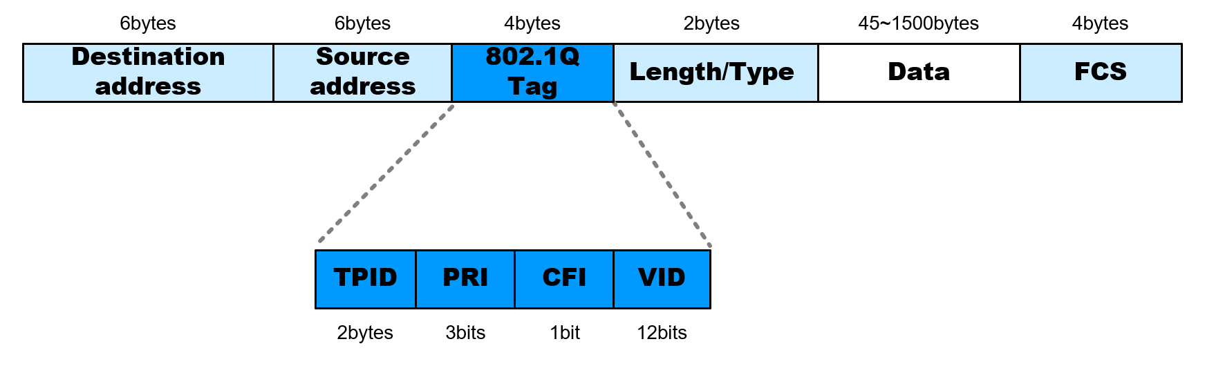
The fields of the header are defined below:
| Field | Length | Name | Description |
|---|---|---|---|
| TPID | 2 bytes | Tag Protocol Identifier | A value of 0x8100 identifies an 802.1Q tagged frame |
| PRI | 3 bits | Priority | A value from 0-7 indicating the priority of the traffic |
| CFI | 1 bit | Canonical Format Indiciator | A value of 0 indicates canonical MAC address format |
| VID | 12 bits | VLAN ID | A VLAN ID from 0-4095, with 0 and 4095 being reserved |
Native VLAN
The 802.1Q standard defines something called a native VLAN. When a switch receives a frame which is not tagged, the switch will implicitely assume the frame is apart of the native VLAN defined in the switch configuration. In most cases, this is VLAN 1.
The native VLAN can be changed, however, switches must agree on what the native VLAN is. Connecting two switches together, each which is configured with a different native VLAN, is considered a misconfiguration.
Trunking
By their nature, VLANs are segregated and a switch will only forward out frames coming into one VLAN interface to other interfaces which belong to that VLAN. To send multiple VLANS to another switch, a dedicated connected interface between each switch would be required to properly forward all VLAN frames.
This is not ideal, and so the concept of trunking is introduced to allow sending multiple VLAN frames over a single physical interface. The interface is typically configured with the appropriate VLAN IDs that it should forward and all forwarding decisions by the switch in a given VLAN will take into account the trunk interface should it be configured appropriately. Downstream switches receiving frames over a trunked interface will be able to inspect the VLAN header to determine how to forward the incoming frames.
Routing
As noteed above, VLANs are segregated and will not forward frames to each other. To get a frame from one VLAN to another requires a routing device. By far the easiest method for routing frames between VLANs is to give an existing layer 3 router an interface on each VLAN and then configure devices to use the router as their default router.